what is used to measure current that is going through a circuit?
How to Mensurate Current
A multimeter provides i of the easiest ways to measure alternating and directly current (Ac & DC). We provide some of the key guidelines . . .
Multimeter Tutorial Includes:
Exam meter basics Counterpart multimeter How does an analogue multimeter work DMM digital multimeter How a DMM works DMM accurateness & resolution How to buy best digital multimeter How to use a multimeter Voltage measurement Current measurements Resistance measurements Diode & transistor test Fault finding transistor circuits
It is ofttimes necessary to know how to measure current using a multimeter. Current measurements are easy to make, but they are done in a slightly different way to the way in which voltage and other measurements are fabricated. Even so current measurements often need to be made to find out whether a circuit is operating correctly, or to discover other facts associated with its current consumption.
Current is one of the basic electric / electronic parameters, and therefore it is oftentimes necessary to measure the current flowing in the ciricuit to bank check its operation.
... both digital and analogue multimeters are able to measure current very hands....
Electric current measurements can exist made with a variety of test instruments, just the most widely used pieces of examination equipment for making current measurements is a digital multimeter. These items of examination equipment are widely bachelor and at very reasonable prices.
Current measurement: basics
Current measurements are made in a different way to voltage and other measurements. Electric current consists of a menstruum of electrons around a circuit, and it is necessary to exist able to monitor the overall flow of electrons. In very simple circuit is shown below. In this in that location is a bombardment, a bulb which can be used as an indicator and a resistor. To change the level of current flowing in the circuit it is possible to change the resistance, and the corporeality of current flowing tin can exist gauged by the brightness of the bulb.

When using a multimeter to measure current, the simply way that tin can exist used to detect the level of current flowing is to break into the circuit so that the current passes through the meter. Although this tin can exist hard at times, it is the best option. A typical current measurement can exist made as shown below. From this it can be seen that the circuit in which the current is flowing has to be cleaved and the multimeter inserted into the circuit. In some circuits where current may oft need to exist measured, terminals with a shorting link may be added to facilitate the electric current measurement.

In society that the multimeter does not change the operation of the excursion when it is used to measure current, the resistance of the meter must be as low every bit possible. For measurements of around an amp, the resistance of a meter should be much less than an ohm. For example if a meter had a resistance of one ohm, and a electric current of 1 amp was flowing, then it would develop a voltage of one volt beyond it. For near measurements this would be unacceptably high. Therefore resistances of meters used to measure current are normally very low.
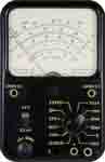
How to measure electric current with an counterpart multimeter
It is quite easy to utilize an analogue meter to measure out electrical electric current. There are a few minor differences in mode that current measurements are fabricated, but the same basic principles are used.
... analogue multimeters are also able to measure current easily and accurately....
When using the analogue multimeter it is possible to follow a number of elementary steps:
- Insert the probes into the correct connections - this is required because there may be a number of different connections that can be used. Be sure to get the right connections as there may be separate connections for very low or very loftier current ranges.
- Set switch to the correct measurement type (i.e. to measure current) and range for the measurement to be fabricated. When selecting the range, ensure that the maximum for the detail range chosen is higher up that predictable. The range on the multimeter can exist reduced later if necessary. Even so past selecting a range that is too loftier, it prevents the meter being overloaded and any possible impairment to the movement of the meter itself.
- When taking the reading, optimise the range for the all-time reading. If possible adapt it so that the maximum deflection of the meter can be gained. In this manner the most accurate reading volition be gained.
- In one case the reading is complete, it is a wise precaution to place the probes into the voltage measurement sockets and turn the range to maximum voltage position. In this way if the meter is accidentally connected without thought for the range to be used, in that location is footling take a chance of damage to the meter. This may not be truthful if it left set for a electric current reading, and the meter is accidentally connected across a high voltage point!
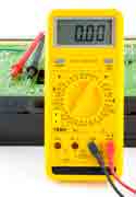
How to measure current with a digital multimeter
To measure electric current with a digital multimeter it is possible to follow a few simple steps:
- Turn the meter on
- Insert the probes into the right connections - in many meters in that location are a number of dissimilar connections for the probes. Frequently one labelled common into which the blackness probe is normally placed. The other probe should be entered into the correct socket for the current measurement to be made. Sometimes there is a special connexion for current measurements, and sometimes a split up ane for either low or high electric current measurements. Select the correct i for the current measurement to be made.
- Gear up main selector switch on the meter switch to the correct measurement blazon, (i.e. current) and range for the measurement to be made. When selecting the range, ensure that the maximum range is above the expected reading predictable. The range on the DMM can and so be reduced as necessary. Even so by selecting a range that is too high, it prevents the meter existence overloaded.
- When the measuring the current, optimise the range for the best reading. If possible enable all the leading digits to not read zilch, and in this style the greatest number of meaning digits can exist read.
- One time the reading is complete, information technology is a wise precaution to place the probes into the voltage measurement sockets and plough the range to maximum voltage. In this way if the meter is accidentally connected without thought for the range used, there is petty chance of damage to the meter. This may not be true if information technology left set for a current reading, and the meter is accidentally connected beyond a high voltage point!
Following these steps it is very easy to measure current using any digital multimeter.
Alternative methods of measuring electric current
The near obvious method to measure current with a multimeter is to intermission the circuit and speedily a meter actually within the circuit. However it is not the only method that tin can be used.
At that place are some methods that can exist implemented that do not require the excursion to be broken and a meter placed in serial.
These methods are often used where it is of import non to break the circuit, and methods which sense the current in 1 manner or another are used.
The accuracy may often be almost as skillful as placing a meter in circuit, but they may require components to already be in identify, or different types of sensor to be used.
Using a series resistor to measure current
This method for measuring current can bring some advantages to some circumstances when it is foreseen that current may demand to be measured on a regular basis inside a excursion.
This current measurement technique entails placing a small resistor of a convenient value into the circuit. Normally i end of the resistor is at ground potential to avoid the risk of either high voltages of accidental shorts to ground while making the test.

Past measuring the voltage across the resistor the current tin easily be calculated.
For example of a 10Ω resistor is placed in excursion and a reading of 100 mV is detected across information technology, then using Ohms Law it can be deduced that the electric current is V / R = 0.1 / 10 = 10 mA .
When using this method of measuring current, the value of the resistor must be sufficiently accurate for the measurements to be made. Any tolerance into e resistor will give a similar tolerance not he measurement. Fortunately many measurements in this situation do not need extreme accuracy, and therefore fifty-fifty ten% resistors will exist sufficiently accurate - 2% may also exist adequate depending upon the tolerances needed.
In the case shown, the series resistor used for the current measurement is placed close to ground, and also it is bypassed with a capacitor to featherbed any bespeak to footing. This is particularly important if the circuit is used at radio frequencies, RF as it will help prevent whatever signal beingness radiated along the test meter leads.
Current measurement technique using a current sensor / coil
If information technology is not possible to pause into the excursion in any way, it is possible to utilise a current sensor.
Electric current sensors normally come in the form of a sensor that is placed around the electric current carrying usher. It is able to notice the current flowing in the conductor and in this manner requite a reading.
These sensors oftentimes come as part of a consummate meter, so it is ofttimes non possible to employ a standard multimeter for this type of test.
At that place are several different types of sensor / meter that can be used this current measurement technique.
- Current transformer: I of the well-nigh mutual forms of current sensor is referred to every bit a electric current clamp. It consists of a split ferrite or soft fe band onto which a whorl is wound - one on each half. The core is passed over the conductor in which the current needs to be measured and the ii halves of the cadre clamped in place. In this way, the assembly acts like a transformer, the clamp coils picking up the magnetic field from the current flowing in the conductor. As the overall assembly is finer a transformer, this electric current measurement technique only works for AC. As well meters using this normally come as a divide "Clamp Meter".
- Hall effect sensor: The Hall Effect sensor using a different engineering. It is able to measure out both AC and DC flowing in a conductor. Information technology is often used in conjunction with oscilloscopes, and high-end digital multimeters, although their employ is becoming more than widespread.
There are other similar current measurement techniques using sensors, but the current clench and the Hall issue sensors are the virtually common.
How to measure air conditioning current with a multimeter
It is ofttimes necessary to mensurate Air-conditioning current. Although the same basic steps are used for taking the Air conditioning electric current measurement every bit when a normal DC measurement is taken, in that location are a few additional points to note.
- Ac setting required: The differences in the measurement result from the fact that the multimeter has to rectify the alternate waveform to enable it to measure AC current. For a digital multimeter the main difference is that the measurement type switch must be prepare to mensurate Air-conditioning electric current rather than DC current.
- Counterpart meters require rectifier: For an counterpart multimeter the situation is a little different. As an counterpart multimeter does not contain any active electronics, the diode rectifier used to rectify the alternating waveform has a certain plow on voltage and this will affect the depression voltage end of some scales. Some meters may not exist able to mensurate AC current, or they will have very restricted ranges.
Although it is not as common to measure electric current every bit it is to mensurate voltage, it is nevertheless and important ability to be able to measure electric current. Also knowing how to mensurate electric current to gain the best of the multimeter is likewise important.
More Test Topics:
Information network analyzer Digital Multimeter Frequency counter Oscilloscope Signal generators Spectrum analyzer LCR meter Dip meter, GDO Logic analyzer RF ability meter RF signal generator Logic probe PAT testing & testers Fourth dimension domain reflectometer Vector network analyzer PXI GPIB Boundary scan / JTAG Data acquisition
Return to Test menu . . .
Source: https://www.electronics-notes.com/articles/test-methods/meters/how-to-measure-current.php
0 Response to "what is used to measure current that is going through a circuit?"
Post a Comment